In this Post, We Provide Complete Model Question and Answer Solution of Class 12 Physics Model Question 2079/2080 SET Issued By NEB.
 |
| NEB Class 12 Physics Model Question Paper 2079 Solution |
Class 12 NEB Physics Model Question
Class 12 Physics Model Question 2079 Released by NEB for 2080 Batch Student is given as:
Class 12 NEB Physics Model Question Solution 2079
Here, We Provide Complete Solution of Model Set Question 2079 of Physics [1021] for Class 12 Prepared by NEB for 2080 Batch. (copyright iswori.com.np)
Sub. code. 1021
NEB-XII 2079(2023)
Model Question
Physics
Candidates are required to give answers in their own
words as far as practicable. Figures in the margin indicate full marks.
Time: 3hrs
Full Marks: 75
Attempt all the questions.
Group A
Rewrite the correct options of each question in your
answer sheet. (11×1=11)
1. The product of moment of inertia and angular velocity
gives
(A) Force
(B) Torque
(C) Linear Momentum
(D) Angular Momentum
2. The bob of a simple pendulum has a mass of 0.40 kg.
The pendulum oscillates with a period of 2.0 s and an amplitude of 0.15m. At an
extreme point in its cycle, it has a potential energy of 0.044J. What is the
kinetic energy of the pendulum bob at its mean point?
(A) 0.022 J
(B) 0.044 J
(C) 0.011 J
(D) 0.033 J
3. What causes earthquakes?
(A) The flow of magma
(B) The expansion of the earth’s crust
(C) The rubbing together of
earth’s plates
(D) Tsunami
4. What percentage of original radioactive atoms is left
after 4 half-lives?
(A) 1%
(B) 6%
(C) 10%
(D) 20%
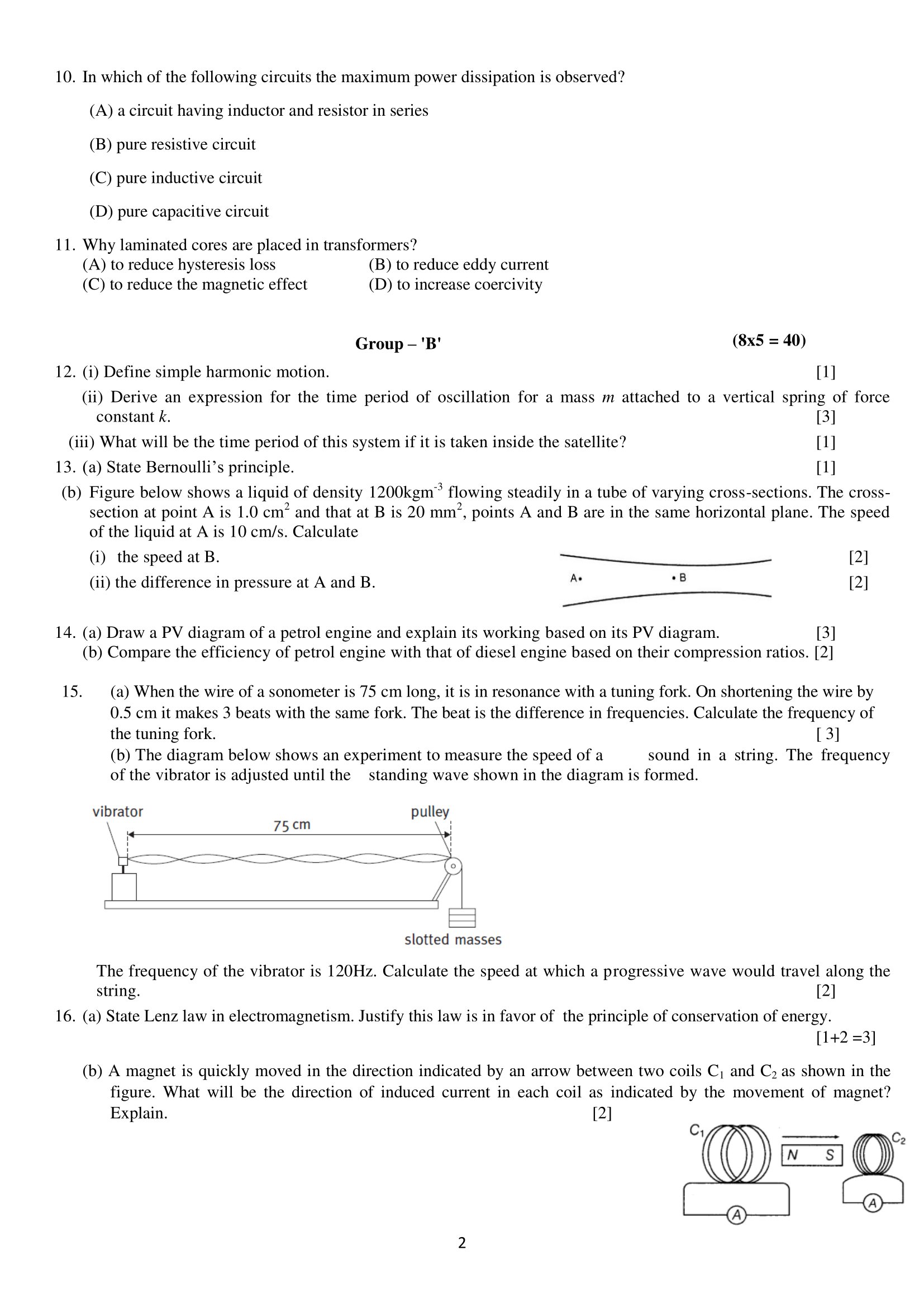
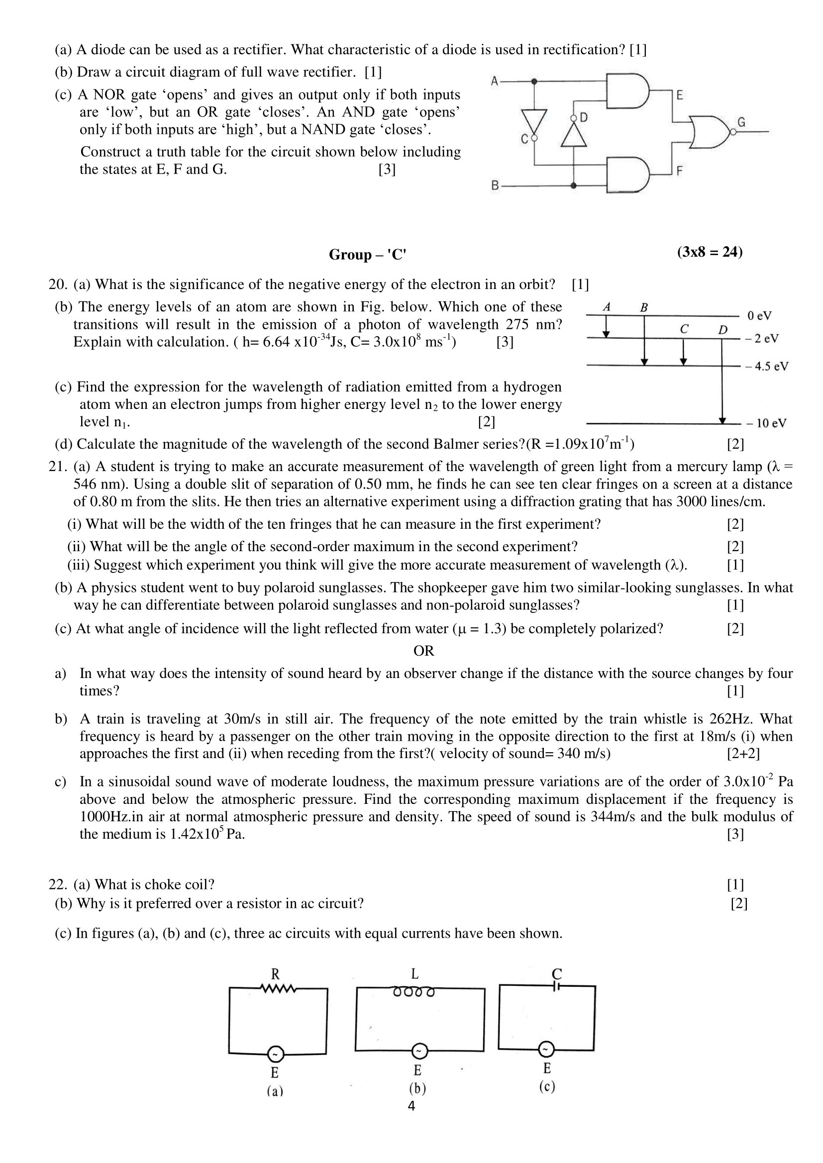
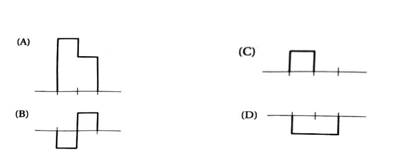
5. Two wave pulses travel toward each other as shown
in the diagram below.
Which of the following diagrams represents the
superposition of the pulses when they meet?
Option C is correct.
6. Which one of the following properties of sound is
affected by the change in air temperature?
(A) amplitude
(B) frequency
(C) wavelength
(D) intensity
7. Internal energy of an ideal gas depends on
(A) volume only
(B) pressure only
(C) temperature only
(D) both pressure and volume
8. In which of the following processes of the gas, work
done is the maximum?
(A) Isothermal
(B) Isobaric
(C) adiabatic
(D) Isochoric
9. The neutral temperature of a thermocouple is equal to
500°C when the temperature of cold junction is 0°C. Percentage change in the
temperature of inversion when temperature of cold junction is equal to 20°C is
(A) 2%
(B) 3%
(C) 4%
(D) 5%
10. In which of the following circuits the maximum power
dissipation is observed?
(A) a circuit having inductor and resistor in series
(B) pure resistive circuit
(C) pure inductive circuit
(D) pure capacitive circuit
11. Why laminated cores are placed in transformers?
(A) to reduce hysteresis loss
(B) to reduce eddy current
(C) to reduce the magnetic effect
(D) to increase coercivity
Group B
12. (i) Define simple harmonic motion.
(ii) Derive an expression for the time period of
oscillation for a mass m attached to a vertical spring of force constant k.
(iii) What will be the time period of this system if it
is taken inside the satellite?
Solution:
(i) The harmonic motion of a simplest type that is of
constant amplitude and of which single frequency is called simple harmonic
motion.
(ii)
Let us consider a light and elastic spring of force constant k. Let its one end
be attached to rigid support (Fig.a) and mass is attached to another end (Fig.b)
as shown in the figure.
Where a load m is attached, the spring extends and let l be
the elongation produced as shown in figure. The restoring force on the spring
is
mg==−kl…(i)
Let the load is pulled down through a small distance y, then
the restoring force F2 is given as
=-K(l+y)….(ii)
The effective restoring force which causes the oscillation
is
F=–
F=-K(l+y)-(-kl)
ma=-ky
or,
or, a∝y…(iii)
where is constant
Hence, the motion of a loaded vertical spring is simple
harmonic.
Time Period
If the load attached on the spring is pulled and lefft, it
will start to oscillate. It’s time period is calculated as given below:
For S.H.M a=−ω2y
For an oscillating loaded spring
where ω is the angular velocity. If T is the time
period of oscillation, then
(iii) If the above vertical mass spring system is taken
into satellite, the time period will not change and remains same as time period
is independent of gravity and value of mass(m) and spring constant(k) always remains unchanged.
13. (a) State Bernoulli’s principle.
(b) Figure below shows a liquid of density 1200kgm-3
flowing steadily in a tube of varying cross-sections. The cross-section at
point A is 1.0 cm2 and that at B is 20 mm2, points A and
B are in the same horizontal plane. The speed of the liquid at A is 10 cm/s.
Calculate
(i) the speed at B.
(ii) the difference in pressure at A and B.
Solution:
(a) According to Bernoulli’s principle, the total
mechanical energy of the moving fluid, which includes gravitational potential
energy of elevation, fluid pressure energy, and kinetic energy of fluid motion,
remains constant.
(b)
(i) Given:
A1=1cm2
A2 = 20mm2=cm2
V1=10cm/s
(i) From Equation of Contunity:
A1 V1= A2 V2
10 × 1 = × V2
Or, V2 = 50cm/s.
Thus speed at B = 50cm/s.
(ii) The difference in pressure between points A and
B can be calculated using Bernoulli’s equation:
We know that , , and . Substituting these values into
Bernoulli’s equation, we get:
Solving for , we get:
Therefore, the pressure at point B is 144 Pa lower than
the pressure at point A.
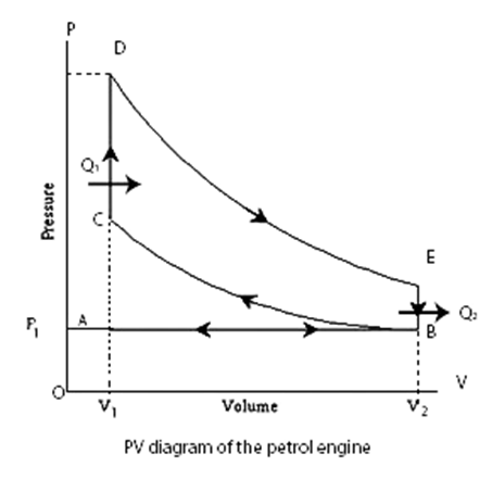
14. (a) Draw a PV diagram of a petrol engine and explain
its working based on its PV diagram.
(b) Compare the efficiency of petrol engine with that of
diesel engine based on their compression ratios.
Solution:
(a) Petrol
engine was developed by otto in 1876 and it consists of four-stroke internal combustion
engine. It uses a mixture of petrol vapor (2%) and air (98%) as working substances.
The P-V diagram of the Otto cycle
is shown in the figure above. The portion AS represents the suction stroke in
which mixture of air and fuel is sucked in at atmospheric pressure. The portion
BC represents the adiabatic compression stroke, the volume decreasing from V2 to
V1. The portion CD represents the result of the explosion of the
mixture. Both temperature and pressure at rising at constant volume. During
this part, the heat energy from combustion is supplied to the engine. The
portion DE represents the working stroke which indicates an adiabatic expansion
from volume V1 to volume V2. During this process the
suffers drop in temperature and pressure. At E the exhaust valve is opened and
pressure falls to atmospheric pressure at B, at constant volume V2.
The portion BA represents exhaust at constant pressure. Then the cycle again
starts to work.
(b) Efficiency of heat
engine in terms of compression ratio =
Where ρ=V2/V1 is called compression
ratio.
Petrol engine have compression ration of 8:1 to 9:1 while
that for diesel engine is 14:1 to 22:1 almost twice of petrol engine.
Thus, compression ration of diesel engine is larger than
that of petrol engine and we can say that petrol engine is less efficient than
diesel engine.
15. (a) When the wire of a sonometer is 75 cm long, it is
in resonance with a tuning fork. On shortening the wire by 0.5 cm it makes 3
beats with the same fork. The beat is the difference in frequencies. Calculate
the frequency of the tuning fork.
(b) The diagram below shows an experiment to measure the
speed of a sound in a string. The frequency of the vibrator is adjusted until
the standing wave shown in the diagram is formed.
The frequency of the vibrator is 120Hz. Calculate the
speed at which a progressive wave would travel along the string.
Solution:
(a) Given:
Length of sonometer wire (l)=75cm=0.75m
Length after shortening(l’) = 75cm-0.5cm=0.745m
Since beat is known as difference in frequency,
f’- f=3
∴ f’=f+3
Now, Length law says
From (i) and (ii)
fl=fl’
or, f×0.75=(f+3)(0.745)
on solving for f
∴f=447Hz
Thus, Frequency of tuning fork is 447Hz.
(b) From Diagram:
Total length (l) = 0.75m
Total Antinodes formed = 6
Total number of complete waves formed (n) =
Then, Wavelength =
And Frequency = 120Hz
∴Velocity = f×λ=12×0.25=30m/s
Thus, the speed of the wave that travels along the sting is 30m/s.
16. (a) State
Lenz law in electromagnetism. Justify this law is in favor of the principle of
conservation of energy.
(b) A magnet is quickly moved in the direction indicated
by an arrow between two coils C1 and C2 as shown in the
figure. What will be the direction of induced current in each coil as indicated
by the movement of magnet? Explain.
Solution:
(a) Lenz law states that the direction of induced
current us such that it opposes the cause which produces it.
Lenz’s law follows the principle of conservation of energy.
The law of conservation of energy states that energy can neither be created nor
be destroyed, but it can be changed from one form to another. Lenz’s law states
that the direction of current is such that it opposes the change in the
magnetic flux. So, an extra effort is required to do work against the opposing
force. This extra effort is converted into electrical energy, which can be
viewed as the law of conservation of energy.
(b) The direction of the current is given by Lenz
law. The direction of the induced current is such that it opposes the relative
motion between coil and magnet.
In the case of Coil C1:
The north pole of bar magnet is moving away while the coil C1will
try to attract it. To attract north pole, it behaves as south pole i.e.,
Clockwise direction.
In the case of Coil C2:
As south pole of bar magnet is moving towards the coil C2
while it will try to repel it. To repel south pole, it behaves as south pole (as
like poles repels) i.e., clockwise direction.
So, the direction of the current will be clockwise as seen
from magnet.
17. (a) State the principle of the Potentiometer. A
potentiometer is also called a voltmeter of infinite resistance, why?
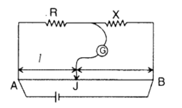
(b) In the meter bridge experiment, the balance point was
observed at J with l=20cm
(i) The values of R and X were doubled and then
interchanged. What would be the new position of balance point?
(ii) If the galvanometer and battery are interchanged at
the balance position, how will the balance point get affected?
Solution:
(a) The basic principle of the potentiometer is that
the potential drop across any point of the wire will be directly proportional
to the length of that portion provided the current is uniform i.e., V α
l.
A potentiometer doesn’t draw any
current when null point is reached. So, it’s measurement is accurate and it can
be regarded as an ideal voltmeter. The voltmeter draws current from the main
circuit to measure the voltage across the circuit element. Thus, the accuracy
of the measurement is affected.
(b)(i) Given:
Length of wire (l) = 20cm
From Meter Bridge:
If both R and X are doubled and
interchanged, the new length that balances be l’ (let).
And Equation (i) becomes:
Equating above Equations, we get:
∴ l’=80cm
Thus, New point of balance will be at 80cm
from A.
(b)(ii) If the galvanometer
and the battery are interchanged the balance point will not have any effect
because the circuit will still acts like meter bridge.
OR
(a) State the two Kirchhoff’s laws for electrical
circuits.
(b) In Meter Bridge shown below, the null point is found
at a distance of 60.0 cm from A. If now a resistance of 5 Ω
is connected in series with S, the null point occurs at 50 cm. Determine the
values of R and S.
Solution:
(a) Two Kirchhoff’s laws are:
(i) First Law: It states that the algebraic sum of
the current at a junction of an electric circuit is zero.
(ii) Second Law: It states that in a closed loop the
electric circuit, algebraic sum of the emfs is equal to the algebraic sum of
the potential difference in the various part of the loop.
(b)
Given: length (l) =60cm=0.6m
We Know, For Meter Bridge:
Or,
When the 5 Ω is connected in series with S, then new
balance point will be l’ = 50cm
Total Resistance (R’) = (S + 5) Ω
Then, From Equation (i) and (ii)
S + 5 =
Or, 2S + 10 =3S
OR, S = 10 Ω
Thus, the value of R is 15 Ω and S is 10 Ω.
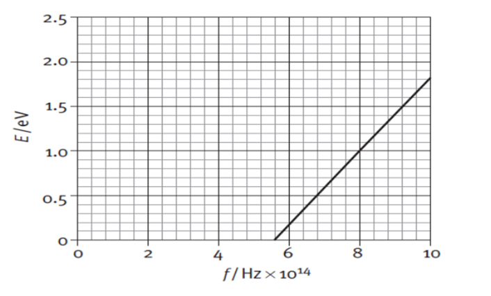
18. The graph below shows the maximum kinetic energy of
the emitted photoelectrons as the frequency of the incident radiation on a
sodium plate is varied.
(a) From the graph determine the maximum frequency of
incident radiation that can cause a photoelectric effect?
(b) Calculate the work function for sodium.
(c) Use the graph to calculate the value of the Planck
constant in Js.
Solution:
(a) Maximum frequency of incident radiation that can
cause a photoelectric effect is 10×1014.
Minimum Frequency of incident radiation that can cause a
photoelectric effect is 5.6×10¹⁴.
(b) From Graph:
Threshold Frequency (f0) = 5.6×10¹⁴
Work Function = h f0=6.667×10-34×5.6×1014=3.73×10⁻¹⁹.
(c) We Know:
Slope = Tangent of the angle made by line with positive x-axis
Slope = tan θ
And, h = e tan θ …… (i)
So, Slope = tan θ =
When, Perpendicular = 1eV then, Base is (8-5.6) 1014
Then, tan θ =
Thus, From Equation (i)
h = e tan θ = 1.6 × 10-19 × 4.166×10-15=6.66×10⁻³⁴.
19.
(a) Figure below shows the experimental setup of Millikan’s oil drop
experiment. Find the expression for a charge of an oil drop of radius r moving
with constant velocity v in a downward direction using a free body diagram.
(b)What will be the expression for the charge of an oil
drop if the electric force is greater than its weight?
(c) Determine the electric field supplied when the
electric force applied between the two horizontal plates just balances an oil
drop with 4 electrons attached to it and mass of oil drop is 1.3×10⁻¹⁴
kg.
Solution:
(a) Let Fe and U be the electrostatic
force and upthrust resp. Let be the viscous force when oil drop
moves with velocity under gravity and also let be the
vscous force when the oil drops moves with velocity under electric Field.
Case I: Under Gravity
U + = W
= W – U …(i)
Case II: Under Electric Field
+ + U = W
Or, + = W-U
Or, + = [ = W – U From (i)]
Or, = –
Or, qE = 6πηr(v1-v2)
Or,
Also,
(b) If Electric Force is greater than its weight (>W),
then the direction of motion of oil drop will be opposite. i.e., it will move
upward instead of downward. Its expression will be:
(c) Given:
Mass (m) = 1.3 × 10⁻¹⁴ Kg
Charge (q) = 4e = 4×1.6×10-19
We Know,
= W [At Balanced State]
Or, qE = mg
Or, 4×1.6×10-19×E = 1.3 × 10-14×9.8
∴ E = 199062.5V
Hence, the electric field is 199062.5V
OR
(a) A diode can be used as a rectifier. What characteristic
of a diode is used in rectification?
(b) Draw a circuit diagram of full wave rectifier.
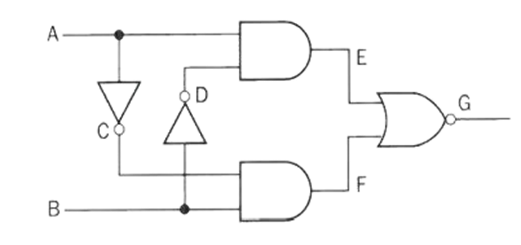
(c) A NOR gate ‘opens’ and gives an output only
if both inputs are ‘low’, but an OR gate ‘closes’. An AND gate ‘opens’ only if
both inputs are ‘high’, but a NAND gate ‘closes’. Construct a truth table for
the circuit shown below including the states at E, F and G.
Solution:
(a) A diode can be used as a rectifier because of its
characteristic of allowing current to flow in only one direction. When a diode
is forward biased, it allows current to flow through it, but when it is reverse
biased, it does not conduct. This property of the diode is used in
rectification, where an AC (alternating current) voltage is converted into a DC
(direct current) voltage.
(b)
(c) Redrawing the above diagram.
From above figure we know that A and B are the input and G
is the output. Let One And Gate be represented as P with input A and and another be represented as Q with inputs and B.
The Output of P is E à
The Output of Q is F à
The Output of G is
When E and F are Input and G is Output:
E | F | G= |
0 | 0 | 1 |
0 | 1 | 0 |
1 | 0 | 0 |
0 | 0 | 1 |
A | B | E= | F= | ||
0 | 0 | 1 | 1 | 0 | 0 |
0 | 1 | 1 | 0 | 0 | 1 |
1 | 0 | 0 | 1 | 1 | 0 |
1 | 1 | 0 | 0 | 0 | 0 |
Thus, When A and B are input and G is Output:
A | B | E | F | G |
0 | 0 | 0 | 0 | 1 |
0 | 1 | 0 | 1 | 0 |
1 | 0 | 1 | 0 | 0 |
1 | 1 | 0 | 0 | 0 |
Group C
20. (a) What is the significance of the negative energy of
the electron in an orbit?
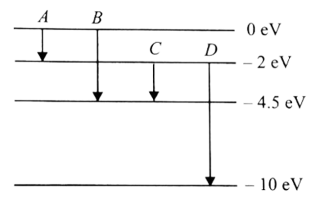
(b) The energy levels of an atom are shown in Fig. below.
Which one of these transitions will result in the emission of a photon of
wavelength 275 nm? Explain with calculation. (h= 6.64 x10⁻³⁴Js, C=
3.0×10⁸ ms-1)
(c) Find the expression for the wavelength of radiation
emitted from a hydrogen atom when an electron jumps from higher energy level n2
to the lower energy level n1.
(d) Calculate the magnitude of the wavelength of
the second Balmer series? (R =1.09×10⁷m -1)
Solution:
(a) The energy of an electron in
the orbit of an atom is negative. It shows that the
electron is bound to the nucleus. Greater the value of negative
energy, more tightly the electron is bound to the nucleus. Binding energy of
a electron is E=−(13.6/n2).
(b) We Know:
Wavelength (λ) = 275nm = 2.75×10⁻⁷
Energy E = hf=
Thus, Energy (E)= 4.5eV [1J = 1.6 ×10⁻¹⁹eV]
Now, From Energy Level Diagram:
For Transition A:
Energy (E) = E1-E2
=0-(-2)
=+2eV
For Transition B:
Energy (E) =0-(-4.5)
=4.5eV
For Transition C:
Energy (E) =-2-(-4.5)=2.5eV
For Transition D:
Energy (E) = -2 – (-10)
=8eV
Thus we can say that the light of photon with energy 4.5eV
can only be emitted when transition takes place from 0eV to -4.5eV energy
level. (Transition B)
(c) The expression for energy when the electron jumps
from higher energy level (n2) to lower energy level (n1) is
given as:
(d) We Know:
For 2nd Balmer Series: n1=2 and n2=4.
Thus, the required wavelength is 4.866nm.
21. (a) A student is trying to
make an accurate measurement of the wavelength of green light from a mercury
lamp (λ = 546 nm). Using a double slit of separation of 0.50 mm, he finds he
can see ten clear fringes on a screen at a distance of 0.80 m from the slits.
He then tries an alternative experiment using a diffraction grating that has
3000 lines/cm.
(i) What will be the width of
the ten fringes that he can measure in the first experiment?
(ii) What will be the angle of
the second-order maximum in the second experiment?
(iii) Suggest which experiment
you think will give the more accurate measurement of wavelength (l).
(b) A physics student went to
buy polaroid sunglasses. The shopkeeper gave him two similar-looking
sunglasses. In what way he can differentiate between polaroid sunglasses and non-polaroid
sunglasses?
(c) At what angle of incidence
will the light reflected from water (m
= 1.3) be completely polarized?
Solution:
(a)
(i)Given:
Wavelength (λ) = 546nm = 546 ×
10-9m
Distance between slits and screen
(D) =0.8m
Separation between Slits (d) =
0.50mm =0.5×
10-3m
We Know:
Width(β) =
β
β=8.736×10⁻³
(ii) Given,
Number of lines per cm (N) = 3000lines/cm = 300000lines/m
Grating Element (a+b) = ==3.33×10⁻⁵
Wavelength (λ) = 546nm = 546 ×
10-9m
Order (n) = 2
We Know:
(a+b)Sin θ = n λ
(3.33×10⁻⁵) Sin θ = 2×546
×
10-9
On Solving,
Sin θ = 0.21
θ=12.3˚
Thus, Angle of second order maxima is θ=12.3˚.
(iii) The second
experiment will give the more accurate measurement of wavelength because the
diffraction grating has a much higher slit separation than the double slit.
This means that the fringes in the diffraction pattern will be much narrower,
which will make them easier to measure accurately.
(b) When light is polarized, the electric
field component of the radiation is restricted to one direction in one plane. So, the
intensity is reduced to half. In case of polarized sunglass the intensity remains
same.
(c) Given,
µ = 1.3
By Brewster’s Law,
tan θp= µ
or, tan θp=1.3
θp=52.43˚
OR
a) In what way does the intensity of sound heard by an
observer change if the distance with the source changes by four times?
b) A train is traveling at 30m/s in still air. The frequency
of the note emitted by the train whistle is 262Hz. What frequency is heard by a
passenger on the other train moving in the opposite direction to the first at
18m/s (i) when approaches the first and (ii) when receding from the first? (
velocity of sound= 340 m/s)
c) In a sinusoidal sound wave of moderate loudness, the
maximum pressure variations are of the order of 3.0×10⁻² Pa above and
below the atmospheric pressure. Find the corresponding maximum displacement if
the frequency is 1000Hz.in air at normal atmospheric pressure and density. The
speed of sound is 344m/s and the bulk modulus of the medium is 1.42×10⁵
Pa.
Solution:
(a) We Know,
…(i)
If Distance is increased by 4 times, then
….(ii)
From (i) and (ii)
If the distance with the source changes by four times, the intensity
gets decreased by 16 times.
(b) Given:
Velocity of source(vs)=30m/s
Velocity of observer(vo)=18m/s
Velocity of sound(v)=340m/s
Frequency from source(f)=262Jz
Now:
Case 1: When Observer approaches first train
Thus, Apparent Frequency is 302.5Hz.
Case 2: When observer recedes from 1st train:
Thus, Apparent Frequency is 228.01Hz.
(c) Given:
Maximum Pressure (Pmax)= 3.0×10⁻²
Pa
Frequency (f)=1000Hz
Velocity of sound (v)=344m/s
Bulk Modulus (β)= 1.42×10⁵ Pa
Now,
Pmax= βAk….(i)
So, k=
From (i):
3.0×10-2 =1.42×10⁵ × A ×
18.26
Or, A = 1.5×10⁻⁸m
Thus, maximum displacement is 1.5×10⁻⁸m.
22. (a) What is choke coil?
(b) Why is it preferred over a resistor in ac circuit?
(c) In figures (a), (b) and (c), three ac circuits with
equal currents have been shown.
(i) If the frequency of e.m.f.be increased, then what
will be effect on the currents flowing in them? Explain.
(ii) What difference do you expect in the opposition
provided by circuits for the current flow in figure (a) and (b) if given a.c.
e.m.f. is replaced by its equivalent d.c. e.m.f.?
Solution:
(a)Choke Coil: A inductance coil with small
resistance which is used to control the current in a.c circuit without much
loss of energy.
(b) Choke coil is preferred over resistor in ac circuit
because the phase difference between current and voltage is Φ=90˚
due to which power loss becomes zero.
i.e., P = EvIvCosΦ = EvIvCos90=0
Since choke coil acts as inductor and has large value of self-inductance
making power dissipation zero(nearly).
(c)
For Circuit A: AC through Resistor only
We Know, V0=I0R.
Since there is no effect of variable frequency. SO, the circuit
will not face any effects.
For Circuit C: AC through Inductor
We Know, V0=I0XL and
Since Current is inversely proportional to frequency. So, On
increasing frequency value of current decreases. Thus, Current in the
circuit B decreases.
For Circuit C: AC through Capacitor Only
We Know, V0=I0 XC and
Since, Current is directly proportional to frequency. So, on
increasing the frequency the value of current in the circuit increases. Thus, Current
in the circuit C decreases.
OR
(a) Define 1 Ampere of current in terms of force between
two parallel current-carrying conductors.
(b) How do you explain the contraction of the solenoidal
coil while the current is passed through it?
(c) A conductor of linear mass density 0.2 g m-1
suspended by two flexible wires as shown in the figure. Suppose the tension in
the supporting wires is zero when it is kept inside the magnetic field of 1T
whose direction is into the page.
(i) Compute the current inside the conductor.
(ii) If the current determined in part (i) is passed
through a 100-turn coil of 100 cm2 area with its axis held
perpendicular to the magnetic field of flux density 10 T and plane of coil
parallel to the field, how much torque is produced?
Solution:
(a) One ampere is that current following in each of
two infinitely long parallel conductors 1 meter apart such that the force
permitter length on each conductor is 2×10⁻⁷N.
(b) When current flows through a solenoid, the
currents in the various turns of the solenoid are parallel and in the same
direction. Since the currents flowing through parallel wires in the same
direction lead to force of attraction between them, the turns of the solenoid
will also attract each other and as a result the solenoid tends to contract.
(c)(i) Given:
Linear Mass density () = 0.2gm/m=0.2 × 10-3kg/m
Magnetic Field Density (B)
= 1T
Since Tension on wire is
0,
So, Upward Force = Weight
Or, BIl sin θ = mg
Or, I =
Or,
Or, I = 0.2×10-3×9.8=1.96×10⁻³A=1.96mA
Thus, Current inside conductor
is 1.96mA.
(c)(ii) Given:
Current(I)=1.96×10⁻³A
Area(A)=100cm2=10-3m2
Number of turns(n) = 100
Flux Density (B) = 10T
Since, Plane is parallel to field, Θ=0
Torque (τ) = BINA Cos θ
τ= 10×1.96×10-3
× 100× 10-3×
Cos0
τ=1.96×10⁻³N/m
NEB Class 12 Physics Model Question Solution 2079/2080 PDF Download
Download
Video Solution
Read More:













answers kata xa?
Euta kura Vanna thiyo
Oi
thanku; we did mistake but we already correct it; again, thankyou for your comment.
Sry 21 b and also check last numerical… Conversion of cm² to m²… Is that correct?
12 b? are you sure?
Plz check your answer of question no 12 b , both you haven't mention about unpolarized light.. or mistaken
ali tala herdai januhos na;
K